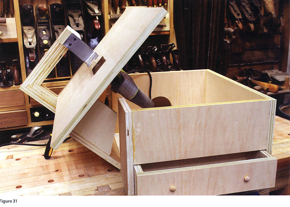
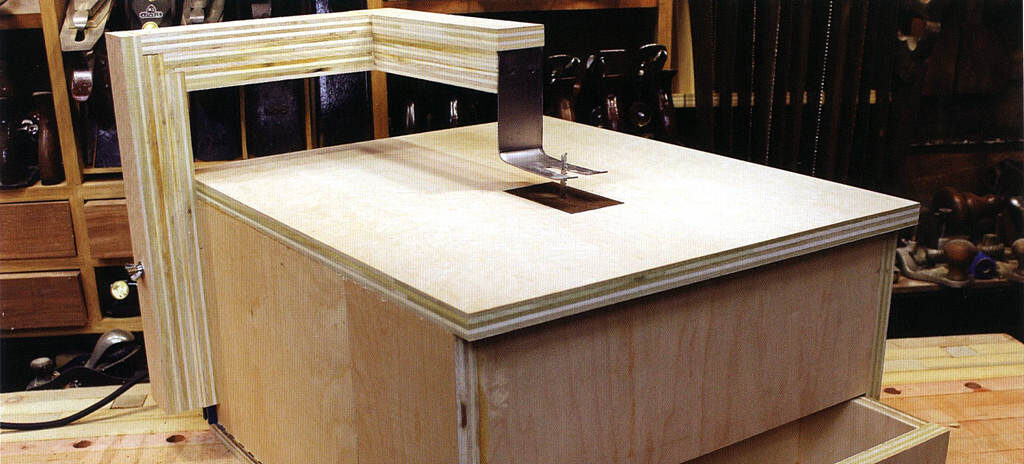
What if we mounted the saw upside-down, like a router in a table? You could cut curves and profiles of any shape or size with greater precision and less chance of damaging bench or flesh. It would turn a handy tool into a far handier tool.
First of all, I wanted the ability to make beveled cuts, and I spent a great deal of time experimenting with tilting carriage designs before. I realized that the best mechanism for the job was already built into the saw. (We’ll get to that in due course.) Secondly, I wanted a greater capacity than the commercial versions offer, allowing me to cut larger workpieces without hitting the guard post. So I made the saw bigger, and I also made the post removable for virtually unlimited capacity. Finally, as with all my homemade tools, I wanted to build in as many bells and whistles as possible. So I added a roomy storage drawer for extra blades, replaceable inserts for cleaner cuts and better blade tracking, an easily adjustable hold-down for extra safety, and a tilting top design that provides fast access to the saw inside.
This benchtop jigsaw has more uses than you might think. It’s one of the most used tools in my shop and I think it will be in yours as well. So let’s get started, shall we?
PART ONE: THE TOP
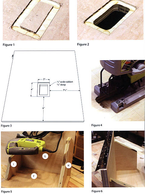 1. Lay out the lines for the rectangular hole in panel G. The rectangle should be 6″ from the front edge of the panel, 11 1/4″ from the rear edge, and 7 1/2″ from the sides (Figure 3).
2. After penciling in the rectangle, insert a 1/2″ straight router bit into a plunge router and set the depth stop at 1/8″. Carefully rout around the inside of your rectangle. Stay about 1/16″ inside your line, then make a second pass to remove the rest (Figure 1).
3. Now set your router so that the bit will plunge all the way through the top panel. Cut out the center of the rectangle, leaving about a 1/2″ rabbet (Figure 2). Square up the corners with a chisel.
4. Flip the panel over and align your jigsaw over the hole so that the blade is in its center. Be sure the base of the saw is parallel to the panel’s sides. Drill four holes through the base and secure the saw to the top panel with screws (Figure 4).
5. Cut part H from corner to corner, creating a triangle.
6. Measure 3″ up one of the long sides of part “I.” From that point draw a diagonal line to one of the corners on the opposite edge. Cut on that line and discard the small triangle scrap.
7. Attach brackets H and I to panel F. Bracket H is should be 3/4″ from the edge of panel F. Bracket I is attached flush with the edge of panel F (Figure 5).
8. Attach panels F, H and I to panel G shown in Figure 5.
9. Attach your piano hinge to the edge of panel F on the top assembly (Figure 6).
PART TWO: THE BOX
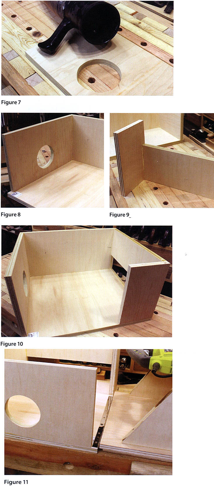 10. Lay a dust collection hose end fitting near the center of panel A, about 1 1/2″ from the bottom edge. Trace around the circumference of the fitting with a pencil and cut the center out with a jig saw. It is best to cut well within the pencil line and then use a spindle sander or rasp to make the hole larger, checking the fit as you do so, until you get a nice friction fit (Figure 7).
11. Next, attach panels A and E to bottom panel B. Panel A will not reach the left edge of panel В (Figure 8).
12. Attach panel C to panel D as shown using glue and brad nails (Figure 9).
13. Finally, flip the C/D panel assembly over and attach it to the A/E/B panel assembly as shown in Figure 10.
14. At this point it would be a good idea to bore a hole through panel A large enough for the end of your saw’s cord to pass through. Position it next to the large dust collection hole so it won’t interfere with the brackets once the top is attached.
A Good Finish…
If you’re like me, you want your homemade tools to look good for a long time. This means applying a finish to shine up all of that nice veneered plywood you used. I prefer a good water based “poly” because it’s easy to apply, dries fast, and is very durable. Two or three coats are adequate for most parts, but add a couple extra coats to areas that will experience more wear.
PART THREE: THE HOLD-DOWN
15. Cut a 2″ x 9 1/4″ rectangle from the thickest steel you can find. Bore a 1/2″ hole 2 1/2 from one of the ends (Figure 12).
16. Use a hack saw to cut from the end to each side of the hole as shown in Figure 12. Use a file to remove any burs.
17. Bend the steel 90° 4 1/4″ from the end you just cut. Then bore two 1/4″ holes through the other end (Figure 13).
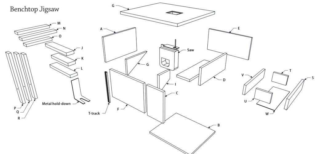
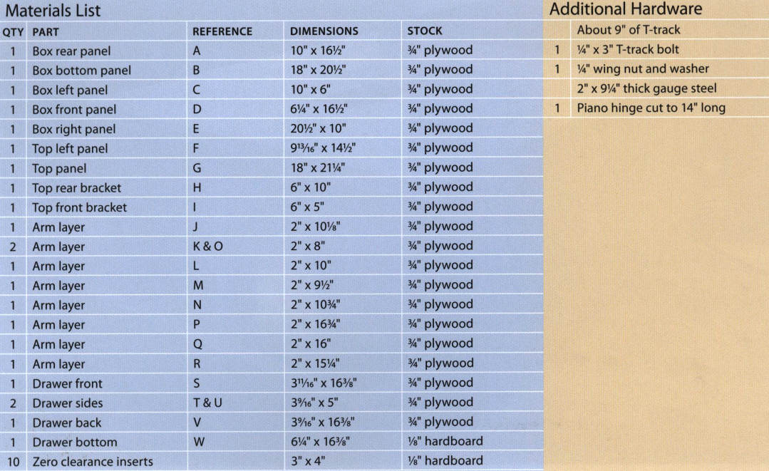
NOTE: There are a lot of parts to the arm, all of which have to be laminated together in the proper order to create a stiff assembly. Label all of your parts with their corresponding letters from the cut list and in Figure 15 before beginning. Always check your parts for square before moving on to the next layer. You may wish to add short headless pin nails to keep each layer from slipping as you add the next on top.
18. Lay out parts L and О as shown in Figure 14.
19. Glue parts К and N on top as shown in Figure 16. Be sure the overhang is exactly 3/4″.
20. Glue parts J and M on top as shown in Figure 17.
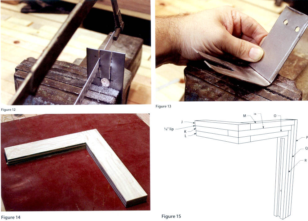
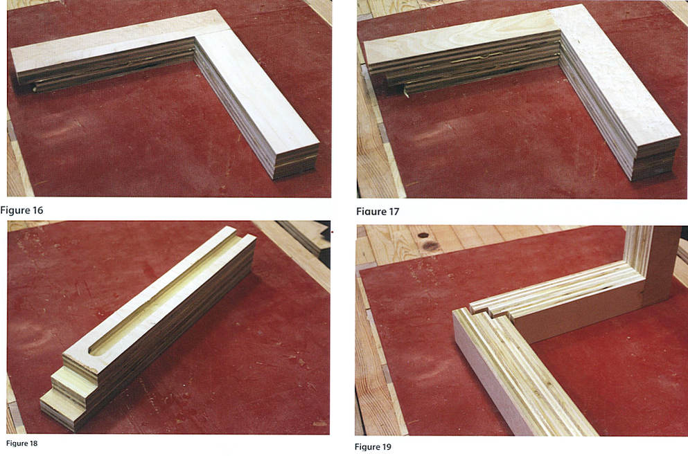
21. Glue parts P, Q and R together as shown in Figure 18. Again, be sure the overhang of each part is exactly 3/4″.
22. Plow a groove down the center of the assembly that is the same width and slightly deeper than the thickness of your T-track. Stop just short of the stepped area (Figure 18).
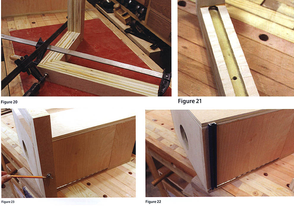
23. Mate the stepped portions of the two assemblies together as shown in Figure 19. Glue and clamp (Figure 20). When it’s dry you may wish to drive some brad nails through the joint from each side for extra strength.
24. Bore а 5/16″ hole through the center of the groove, 5″ from the end. Insert a T-bolt through that hole (Figure 21).
25. Attach a piece of T-track to the rear of the left side of the unit 3/4″ from, and parallel to the edge. (Figure 22).
26. Finally, slide the arm over the T-track, allowing the head of the T-bolt to slip into the track. Secure the arm in place with a washer and wing nut (Figure 23).
PART FOUR: THE DRAWER
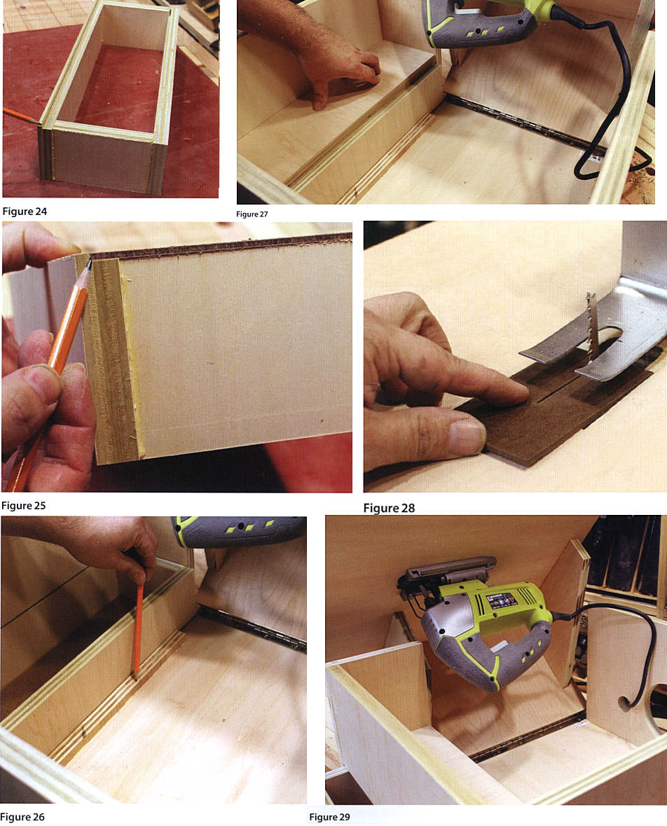
27. Raise your table saw’s blade 1/2″ above the table. Set the fence 3 9/16 from the blade and pass part S through the blade, cutting a 1/8″-wide rabbet along one of the long edges. If you have a thin-kerf saw blade you will have to take two passes to remove all of the waste. You can see the completed rabbet at the pencil point in Figure 24.
28. Assemble the four sides of the drawer (panels S, T, U and V) as shown in Figure 24.
29. Attach the hardboard bottom (panel W) so that it sits in the rabbet as shown in Figure 25.
30. You should either bore a finger hole or install a small pull in the center of the drawer front.
31. Insert the drawer into the saw’s box and glue a strip of wood to the bottom panel behind the drawer as a stop (Figure 26).
32. Next, cut a piece of plywood (5 1/8″ х 16 1/2″) to fit above the drawer as a dust shield. Be sure that this shield does not interfere with the wooden bracket (I) when you close the top of the unit. Secure the dust shield in place with brad nails driven from the outside of the box (Figure 27).
33. The materials list includes several pieces of hardboard to use as replaceable inserts. You’ll want them to fit snugly in the saw’s mouth opening, so it is better to cut them slightly oversized, sanding the edges down until they fit. To replace an insert, turn on the saw and carefully slide it into the recess, cutting a kerf as you go (Figure 28). If you find that the inserts pop out during use, they are too small for the opening. A solution may be to drive some short flat-head screws through the insert and into the rabbet beneath, countersinking the heads. If you choose this option, be sure to bore the screw holes in all of your inserts in the same place so that they will all align with the same holes in the rabbet. Perhaps, in that case, you should make a couple dozen inserts, drilling the screw holes through the whole stack at once, so you will never have to repeat the process.
