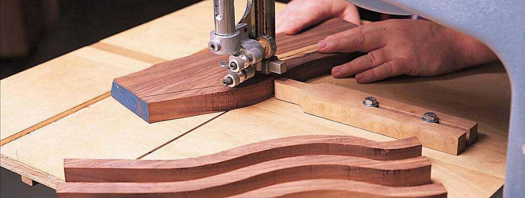
This versatile and inexpensive jig is guaranteed to spiff up your saw.
If you use ihc band saw merely for freehand sawing of curved components and an occasional resaw chore, you’re selling short one of your shop’s most versatile machines. Just adding an oversize table will improve your work. Add accessories to that table, and you can split cylinders or turnings, saw parallel curves, saw patterns, cut accurate circles and crosscut round stock. Tricked out, the band saw gains the status it deserves.
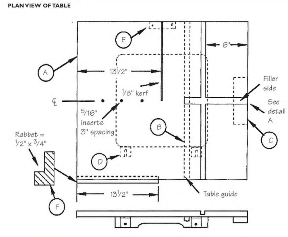
My master jig was designed for the average “small’’ machine. If your unit has a 12″ to 14″ cutting capacity from the blade to the post and your table measures about 12″ to 14″ square, you should be able to make my jig with a few alterations.
Before building this jig, check two things on your saw. With the trunnion at 0. Make sure the angle between the saw blade and the table is 90”. Also, verify the saw blade and the miter-gauge slot are parallel.
START WITH THE TABLE
Cut a piece of cabinet-grade plywood for the jig’s table to size for your saw, then use the table saw to form the kerf for the blade (see “The Table” diagram). Next, form the T-slot for the pivot slide centered on the table. Cut the 1″ x 9″ slot using your table saw to define the width of the slot (stop short of the final length). Extend the cuts with a handsaw. Remove the waste with a chisel. Now widen the bottom half of die slot io 2″ with a dado or by repealed passes with a saw blade.
The cuts make 3/8″-deep by 1/2″-wide rabbets (detail A).
Next, use your table saw to cut the slot for the miter gauge. Locate it 6″ away from the outside edge of the table. Its depth and width must match the bar of your miter gauge.
Drill holes for the three 5/16″ threaded inserts as shown; install them through the bottom of the table until they are almost flush with the table’s surface.
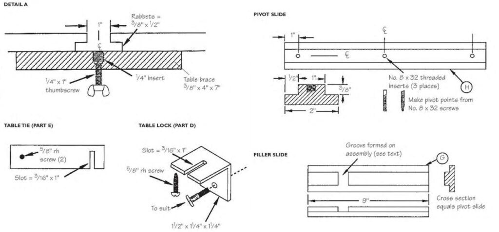
TABLE GUIDE
On the underside of the table, attach a table guide (B) that slides in the machine’s miter slot. Here’s how: Put the table guide in the saw’s miter slot, then position the jig’s table so its right edge and the guide arc parallel. Secure the guide by lacking through the table, then attach the guide permanently with four No. 4 x 3/4″ fh screws from the bottom of the guide and glue. Drill shank anti pilot holes for the screws so they won’t split or spread the guide when installed.
ADDTHE BRACES
Prepare the pan for the fence brace (F) and then cut the 1/2″ x 3/4″ rabbet. Attach the brace to the table with glue and 4d finishing nails. Now cut the table brace (C) to size and install the 1/4″ threaded insert as shown, then glue and clamp the brace in place until the glue sets.
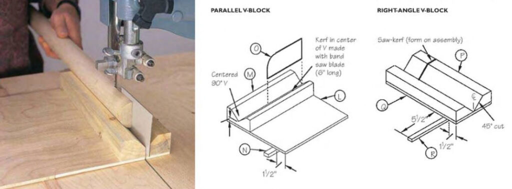
TABLE LOCKS AND TIE
Use aluminum angle with 1¼” legs for the table locks. Because some pivotguided work requires good alignment between blade teeth and pivot point, a slot in die lop leg of the angle is needed. This allows the jig’s table to be moved to allow for blade width and tracking adjustment.
Drill boles through the vertical leg of the locks to match the holes that are in the table for adding aftermarket accessories. Use bolts to secure the locks to the saw’s table and put the jig’s table in place. Use an awl to pierce the underside of the table at the front end of the slot in the lock and then install the 5/8″ rh screws.
Make the table tic from aluminum strap. Attach it to the underside of the table so it spans the kerf. The tie keeps the table level on both sides of the kerf.
THE PIVOT AND FILLER SLIDES
The filler slide (G) and pivot slide (H) have the same T-shaped cross section and dimensions, so a good procedure is to start with parent stock that is 25″ long and cut pieces to length after rabbeting the edges of the material. When the filler slide is in place, you’ll sec that it runs across the miter-gauge groove in the jig’s table. So mark the location of the groove on the slide and then notch it so it won’t interfere when using a miter gauge.
Mark the locations of the three No. 8 x 32 tpi threaded inserts that are needed in die pivot slide. Install the inserts so they’re flush with the top surface of the slide. Make the pivot points by removing the head from No. 8 screws. Chuck one of them in a drill press and form a point with a file, or grip the screw in a portable drill and spin it against a turning grinding wheel.

MAKING THE FENCE
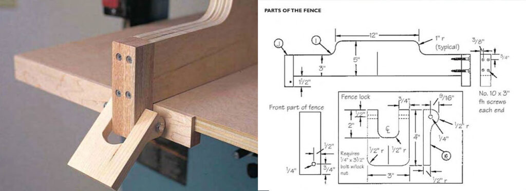
Cut stock for the fence body (I) to overall size. Shape the top edge on the band saw and smooth it with a drum sander. Next, cut the ends (J) to size and install the rear one with glue and four No. 10×3″ fh screws. Be sure to drill adequate shank and body holes and to countersink carefully before driving the screws. Before installing the front endpiece, carefully locate and drill the hole that is needed for the fence lock (K).
Now cut the fence lock to size, and accurately locate and drill the 1/4″ hole. Lay out the shape of the centered opening and saw away the waste with a hand saw. Then use the hand saw to shape the lock’s edge profile hut don’t try to shape the rounded end exactly at this point. Instead, work by hand with sandpaper to dress the end so that, when the lock is pivoted downward. the rounded end will bear firmly against the fence brace to secure the fence’s position.
ACCESSORIES
Cut material for the V-blocks (M and P) to size. Form the Y-shaped trough by making a 45° bevel cut along one edge of slock that is 24″ long and then halve the piece. For the parallel V-block, use glue and brads to attach the two pieces to the base so they form a \-trough.
Prepare the base (L) and attach it to the bottom of the block with glue and brads. Size the guide (N) so it will lit snugly in the table’s miter-gauge slot. A little on the snug side is good so the accessory won’t move.
To set up the parallel V-block, put the guide in place in the table groove and position die block-base assembly so the cm path of ihe saw blade will be on ihe center of the V-cut. Mark the position of the guide and attach it to the underside of the base using glue and brads. Place the accessory in position and, with a fine saw blade mounted, saw a kerf about 6” long.
Make the splitter (O) by rounding off the lop, forward edge and smoothing the edge. The splitter should fit lightly in the kerf. If not, cover the bottom edge with plastic tape to thicken it.
For the right-angle V-block, shape the guide (R) so it will ride smoothly in the table slot. Put the guide in the slot and position the V assembly (P and Q) so the angle between its forward edge and the side of the saw is 90°. Mark the position of the guide and then attach it to the block with glue and small nails.
TWO SAWING GUIDES
Shape the front ends of the guides (S and U) on the band saw and smooth the sawed edges with a drum sander. Drill a 5/16″ end hole for the slot and saw out the waste. The guide is secured to the jig’s table with 5/16″ bolts that thread into the inserts installed in the table. The pattern-sawing guide is shaped like the one made for parallel curves except that the slot is shorter and the business end is notched to fit the saw blade that is used. The riser (T) is needed so the guide will be elevated above the workpiece.

