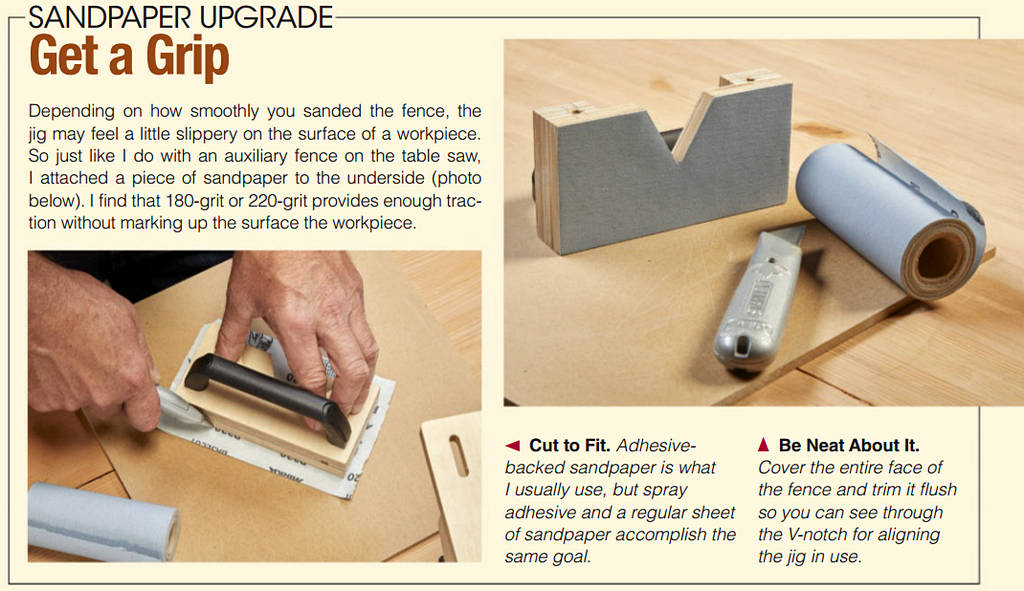
My palm router probably has just as many joinery miles on it as it does for profiling and shaping. Fitted with a straight bit, I can make dadoes, rabbets, grooves — and mortises. The sticking point is coming up with an accurate way to control the router.
The solution is to make a jig. I’ve made mortising jigs (or templates) that have ranged from quick one-offs to complex adjustable gadgets. They have all worked. What I dislike is the setup.
The jig needs to be clamped in the correct location on the workpiece (which is also clamped in place) prior to every cut. All that clamping and releasing adds up. Enter Chris Fitch.
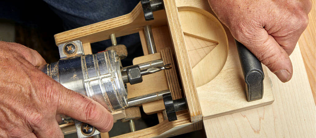
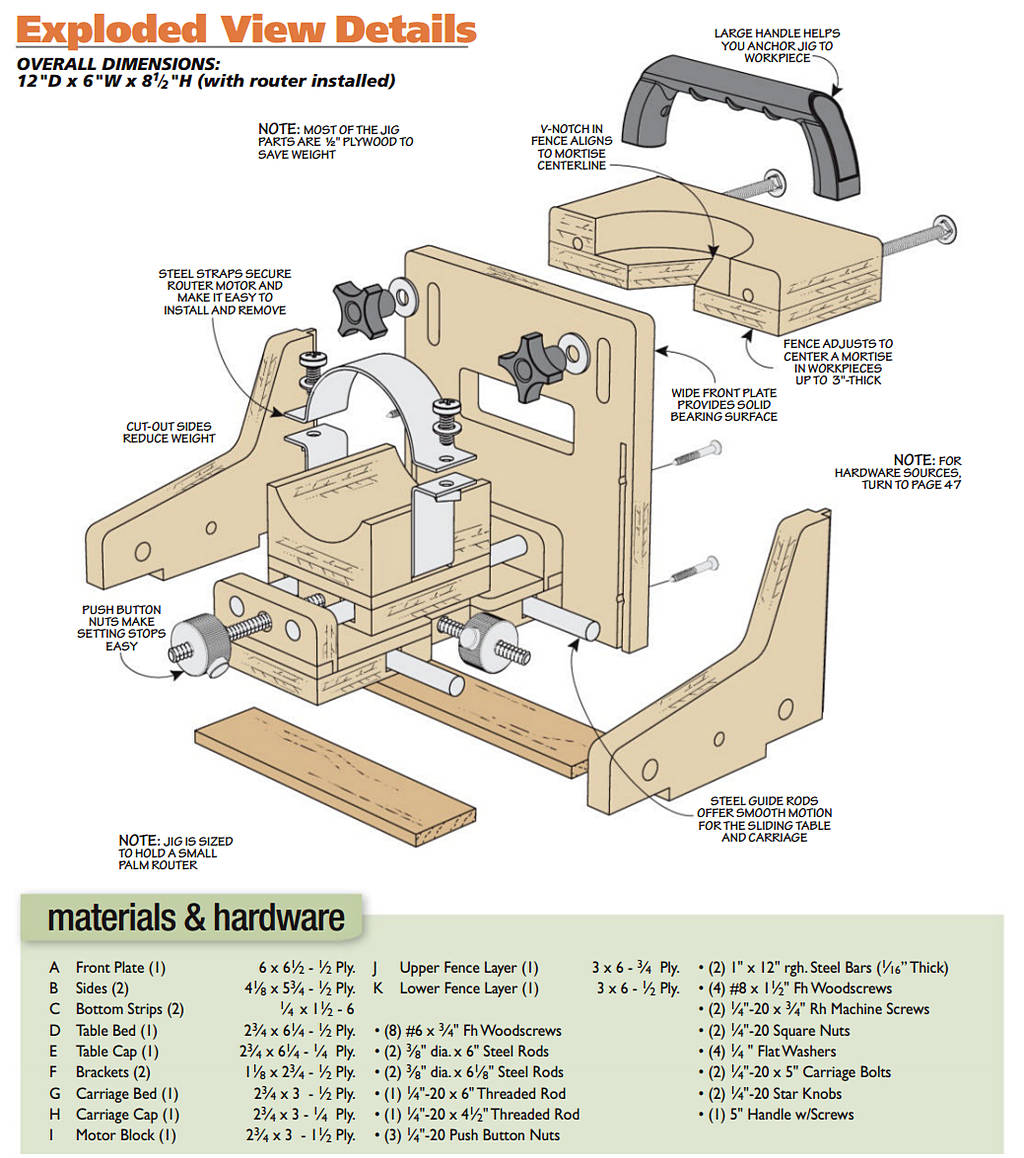
The jig you see here tackles the issue by working more like a biscuit joiner, or Festool Domino joiner. The router is attached to the jig and used like a hand-held power tool. The drawing on the next page shows the overall concept. The router moves forward, back and side to side on a pair of carriages and guide rods. A fence in conjunction with a series of stops controls the location and the size of the mortise.
The challenge is making a jig that’s versatile to work on a variety of applications without letting it get too big and cumbersome to use well. As we go along, you’ll see how this jig checks all boxes. Then take a look at the article on page 8 to find out how to integrate the jig into a joinery technique.
Compact, Stable Jig Base
As I mentioned earlier, there are four components that make up the jig: the base, a pair of carriages, and the fence. A natural place to begin is the base (Figure 1 above). As a hand-held tool, keeping the jig lightweight and compact is high on the priority list. As a result, many of the pieces are made from 1/2″ Baltic birch plywood (rather than 3/4″ plywood pieces). The material is flat, stable, and strong.
FRONT PLATE. The front is a wide plate that serves as a reference surface for the jig against the workpiece. Near the top, a window in the front provides visibility and access for the router bit.
Also near the top are short slots that provide adjustability for the fence, as you can see in Figure 1a. To cut these, I prefer to drill the ends at the drill press. Then connect the dots at the router table with a straight bit.
While you’re at the router table, you can set up to cut stopped grooves along the edges (also show in Figure 1a). The grooves register the sides that we’ll get to here in a bit. Ease the upper comers and drill countersunk screw holes drilled from the outside face to complete the work on the front.
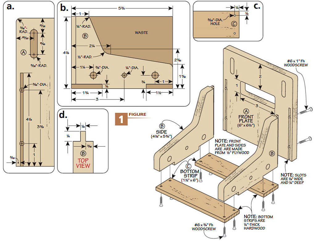
SIDES. The the L-shape of the two sides helps reduce weight and provides access to grip the router comfortably. However, as Figure lb shows, you need to keep them as rectangular blanks for the time being.
First up is to form a tongue on the front edge, as shown in Figure 1c. This is sized to slip into the stopped grooves in the front. My goal is a for a snug fit.
A set of holes along the bottom edge house a pair of guide rods and a length of threaded rod for two stop nuts. These need to be perfectly aligned. In order to do this, I taped them together with double-sided tape and drilled the holes at the drill press.
The taped-up sides come in handy for the next couple of steps, too. At the table saw, notch the lower edges. Hold the sides against an auxiliary fence on the miter gauge and set the rip fence as an end stop. A set of hardwood strips added later fits into these notches adding rigidity and stability to the sides.
With the other details addressed, you can now cut the sides to the profile shown. I did this at the band saw. Clean up the edges with files and sandpaper.
BOTTOM STRIPS. Cut hardwood strips to fit the notches. While 1/4″ plywood could work, stout hardwood like maple is less likely to flex.
SQUARED ASSEMBLY. These pieces can now be brought together. Your focus is on squareness. The sides need to be square to the front. Additionally, the bottom should be square to the front as well. Paying attention to this provides a solid foundation for smooth, accurate operation of the jig once it’s complete.
Glue the sides into the front and add the screws. At the bottom, I just used screws in case I needed to remove the strips while working the rest of the jig.
SLIDING TABLE
The motion of the router is controlled by a pair of carriages or sliding tables. The lower one shown in Figure 2 I’m calling a “sliding table” handles the lateral movement. It engages with the base we just completed.
TABLE BED & CAP. Start by cutting the bed and cap to the same size. Both of these are Baltic birch plywood. However the bed is 1/2″ while the cap is 1/4″. They aren’t glued together just yet.
You need to cut a pair of dadoes in the bed to hold steel guide rods. Two things are important here. The width of the dadoes should match the diameter of the rods, as in Figure 2c. Any play will translate to wiggly action of the router in the jig. You don’t want wiggly.
The other detail is the spacing of the dadoes, as you can see in Figure 2e. These need to align with the holes in the sides. Make test cuts in scrap if you need to in order to get the settings right.
Glue on the cap taking care to keep glue out of the dadoes. Then set up to cut a dado across each end (Figure 2d).
These are anchor points for brackets to hold the upper router carriage.
Take a break from the table saw to drill a hole through the middle of this assembly. The hole allows a threaded stop rod to pass through. Here again the location of the hole corresponds with the hole in the sides.
At this point, install a dado blade to cut the waist on the bed and cap. This is shown in Figure 2e. This narrow section adds clearance for a pair of stop nuts that determine the mortise width. Note the edges of the waist are softened.
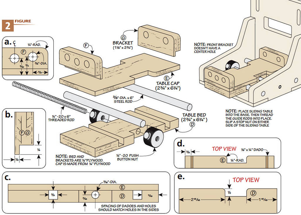
BRACKETS. Two small brackets wrap up the woodworking portion of the sliding table. Since these are small pieces, I began by forming a tongue at one end of a long blank for safety. Size the tongue to fit snugly in the dadoes of the cap, as in Figure 2b. Then cut the brackets to their final length.
As with the sides, these have holes drilled in them for guide rods and a stop rod. The dimensions for these are shown in Figure 2a. You know the drill: tape them together before heading to the drill press. Ease the upper comers to eliminate a harsh edge.
HARDWARE. It’s time to turn your attention to the metal bits of the sliding table. The two steel guide rods are precision ground so they’re straight, consistently sized and smooth. Cut them to match the width of the jig base.
A threaded rod passes through the sliding table and anchors in the base. As you fit the threaded rod in, position a push-button nut on each side of the sliding table. These are amazing bits of hardware. When you depress the button, you can slide the nut along the rod for quick adjustments. Release the button and you can still rotate the nut for fine tuning. The spring tension keeps the nut from moving during use.
I used a bit of instant glue to lock the threaded rod to the sides so it doesn’t move around during use. You could also use a little dab of epoxy, too.
One final thing: rub a little paste wax (or a spray dry lubricant) on the guide rods. This helps the table to slide along easily while routing.
Router Carriage
The second moveable component is the router carriage. Since it holds the router motor (and bit), it provides accurate adjustment for the depth of cut. Take a moment to go over the drawing above. There are some familiar elements you’ll recognize from the sliding table. I’ll point out what’s new, too.
Making the carriage bed and cap follows the same process as the sliding table. The only difference is the spacing of the dadoes, as in Figure 3b. As a reminder, the spacing matches the holes you drilled in the brackets earlier.
SOMETHING DIFFERENT. The hole for the stop rod doesn’t pass through the carriage bed. That’s because the depth is set with one stop nut at the back of the jig, as shown in Figure 3. Glue the cap to the base at this point.
MOTOR BLOCK. The router motor rests in a thick, shaped plywood block that gets screwed to the carriage. There are two main details to address. First, you need to cut a dado across the bottom of the block. This is shown in Figure 3c. The dado is sized to accept a length of steel bar that secures the motor.
The second detail is shaping the block to match your router motor. I used calipers to determine the radius of the motor and marked it on the block.
Rough out the waste at the band saw. Spend some time to get a good fit with files and sandpaper. In addition, you need to pay attention to the orientation of the motor in relation to the operation. The motor needs to rest parallel to the carriage bed and square to the front of the carriage so you end up with mortises that are square and plumb.
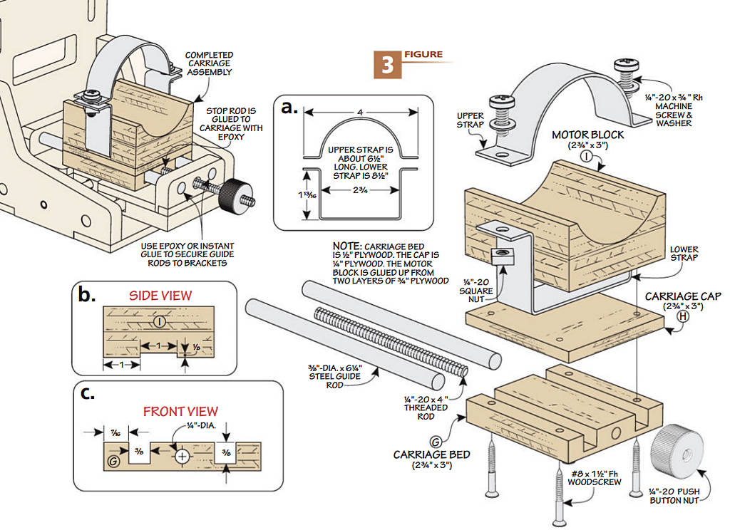
METAL BITS. Like before, the guide rods and stop rods are cut to size. To secure the router, you need two lengths of the steel bar stock, as you can see in Figure 3a. One piece is bent into a squared-off U-shape. A machinist vise comes in handy to bend the strap at right angles.
The upper strap is bent into a semicircular form. I opened the jaws of the vise a bit to help bend the bar to an even curve. Compare the profile to your router motor to get a snug grip.
Bend an ear on the ends of the bars to create a flat mating surface. After you ease the sharp comers with a file, drill holes for the machine screws, washers, and nuts that do the work of securing the router to the block.
ASSEMBLY. Fit the lower bar around the block and attach these to the carriage assembly with screws only. Next set the carriage in place on the jig. Add a bit of epoxy to the holes in the brackets to keep the guide rods from working loose over time. Press the guide rods into place. In a similar manner, place a little epoxy in the hole in the base for the stop rod and thread the stop rod home. The stop nut can be added last.
ADJUSTABLE FENCE
The fourth and final component of the mortising jig is the adjustable fence. As you can see in Figure 4, this is the simplest portion of the project, and a fitting way to wrap it up.
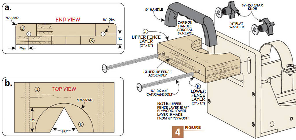
TWO LAYERS. The fence consists of two layers of plywood. Before you glue them together, there’s a step to take on each one. The details are shown in Figure 4a. The upper layer has a half circle cutout. This opens up the fence for better visibility. The bottom layer includes a V-shaped notch, as you can see in Figure 4b. This is used to line up the jig with the mortise centerline on the workpiece. After cleaning up the cut lines, glue the layers together.
The fence connects to the jig with long carriage bolts, washers, and knobs. Drill holes through the fence to align with the slots in the front of the jig (Figure 4b). I rounded over the upper side edges before attaching the handle (Figure 4a).
Finishes on a shop project are subjective. I prefer a couple coats of wipe-on varnish to create a smooth surface and added durability. You’re ready to put the jig to use.
