Router lifts are one of those things that would blow an old-timey woodworker’s mind. Actually, routers themselves would probably impress them even more. But the ability to adjust that router far more precisely than by hand, with the lazy pleasure of never having to bend over … well that’s the ultimate “how did I ever live without this” kind of tool. Then the old-timer would discover that such a workshop luxury costs about as much as he spent on his best horse and the barn it lives in. Well, let’s just say it’s no wonder that Thomas Chippendale didn’t own a router lift. But as a modern woodworker with a modern workshop full of modern tools, I refuse to lift my own router! So I designed my own router lift.
I’m obviously not the first guy to design a router lift, but my homemade version has a few features that make all the difference to me. For one thing, it tracks smoothly and accurately. But that didn’t happen by accident; it took a lot of thought. I used ball-bearing drawer slides for smooth operation, combined with a beveled hardwood track that, when engaged with the turn of a knob, cancels out any unwanted movement that the drawer slides may allow. The router itself is secured to the movable carriage with some custom mounting blocks and a pair of large hose clamps, making it easy to remove and replace as needed.
- Router
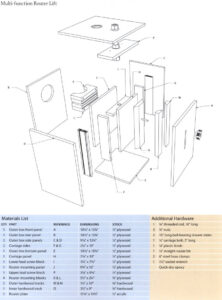
- Router Lift blueprint
- Router Lift blueprint
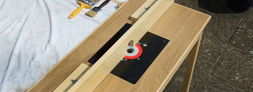
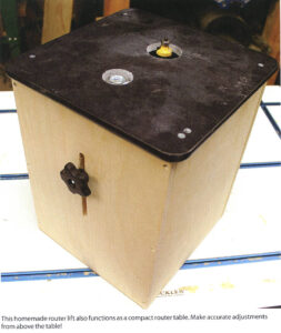
To adjust the lift, you simply turn a nut embedded in the top of the unit with a common socket wrench. The coarse threads on the lead screw raise the router quickly when desired, while giving you the ability to make the finest of adjustments. The router itself is enclosed in a box, dampening noise and greatly improving lower dust collection by means of a 4″ outlet in the rear. The airflow from the dust collector also keeps the motor running cool under heavy use. But the most noteworthy feature of this lift is how it can be used as a standalone unit, a minirouter table with full lift and dust-collection features. You can drop it in the wing of your table saw or into a router table. You can store it on a shelf and set it on the bench when you need it. You can even take it with you for routing on the go, if you’re into that kind of thing.
In this chapter I’ll walk you through the build, help you select a router, and even give you some tips on making your own router plate. You’ll save a few hundred bucks and say goodbye to the old days when you used to lift your router by hand!
PART ONE: THE CARRIAGE
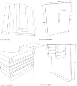
STEP 1: Draw a pencil line lengthwise down the center of the box front panel (A) (Figure 1). Measuring from one of the short sides, mark across your line at 4″ and 8″. These points will be the ends of your slot. Drill them out with a 3/8″ bit (Figure 2).
STEP 2: You’ll have to remove the material between your holes to complete the slot. There are several ways to do it: You can continue to drill holes right on down the line then clean the slot up with a chisel (Figure 3), or you can use a jigsaw or scrollsaw to cut out the waste. When you’ve finished, set the panel aside.
STEP 3: Find some scraps of 3/4″-thick hardwood that are 9″ long. The width of the hardwood pieces aren’t that important, but the wider they are, the easier they will be to bevel (especially because one piece will have a bevel on two sides). I set my table saw blade to 45° and ripped two pieces about 1 1/2“ wide, with a bevel along one edge. I ripped a third piece around 3 1/2″ wide, with two beveled edges (Figure 4). If yours are a little undersized, it’s no big deal. Just make use of whatever scraps you have. These three parts will make up the wooden track at the front of the lift.

STEP 4: Locate your carriage panel (H). Put some glue on the back of the double-beveled hardwood piece that you just cut and roughly center it on your panel with one end against a short edge. Use a combination square to check both sides of the block, making sure it is perfectly centered on the panel, and parallel to the panel’s edges (Figure 5).
STEP 5: Those two carefully joined parts make up the beginnings of your carriage. Now add sides, which are parts F and G on the materials list. Glue them to the panel’s edges, pointing away from the beveled block (Figure 6). You can clamp them in place to dry, or speed things up by shooting a few brad nails in them. Then set it aside for a bit.
Check Your Work
As you assemble this project, carefully check the position of the parts. Make sure they are centered if the instructions call for it. Is everything square and parallel? It was designed so that everything will work smoothly if you show proper care as you build it!

PART TWO: LOWER LEAD SCREW BLOCK
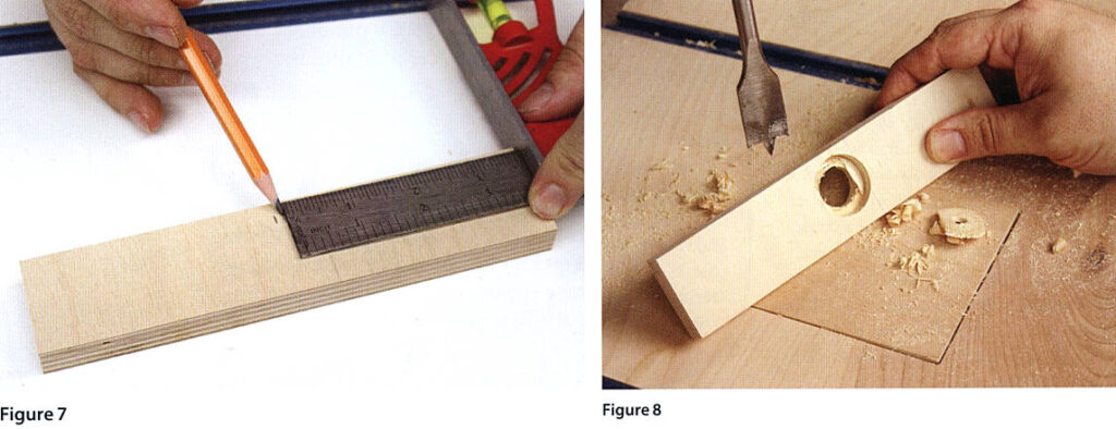
STEP 6: Locate part I and, using your method of choice, find its exact center along its length (Figure 7). Now measure 7/8” from one of the long edges and mark where it meets your center line.
STEP 7: Head over to the drill press and chuck up а 1 1/8” spade bit. Set your depth stop to bore two thirds of the way through the plywood. (The brad point of the bit can extend farther.) Drill into the center of the piece, then wander around the shop until you locate that drill press chuck key you’re always misplacing, and use it to swap over to a 3/4” bit. Stick that bit’s point in the little hole made by the larger bit’s point, and bore the rest of the way through, creating a nice stepped hole (Figure 8).
STEP 8: Someday we’ll make a jig to drill holes shaped like octagons, but for now we’ll just modify this one. Slip your 3/4″ threaded rod through the hole and tighten a nut on each side of the workpiece, pinching the wood in between. Now, with a pencil, trace around the nut that’s covering the larger of the two holes (Figure 9). After you remove the hardware, get out a chisel and carefully trim to the line, removing the waste until you have a nice nesting spot for one of the nuts, which you will now epoxy in there, ensuring that it sits flat (Figure 10).
STEP 9: While that dries, lay your carriage flat on the bench, beveled block up. Get out your drawer slides and throw away the directions because you probably don’t understand any of the five languages they are written in. Separate them into halves and lay the wider portion of one slide next to the carriage with the rubber bumper pointing toward the bottom (Figure 11). You don’t need a million screws, just three or four per side. It’s important that you use a center punch to create a little pilot hole for each screw. You don’t want them to wander off center as you drive them home and throw your drawer slide out of alignment. Attach a half drawer slide to each side of the carriage.

They Aren’t Just For Sliding Your Drawers
I use ball-bearing drawer slides for all sorts of stuff around the shop. They’re smooth, durable and accurate enough to create sliding mechanisms for woodworking jigs. You’ll find them in a lot of home centers, cabinet suppliers and woodworking outlets. I like to keep a couple sets of different lengths on hand because I’m always finding new uses for !
PART THREE: THE OUTER BOX
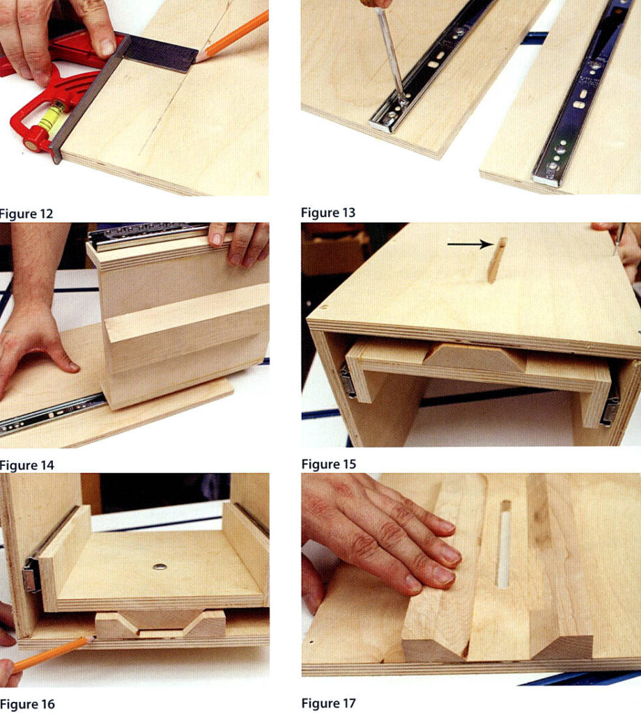
STEP 10: Draw a line on panel C that is 2 1/4″ from, and parallel to the right (long) edge (Figure 12). Do the same on the left edge of panel D.
STEP 11: Place the narrow halves of your drawer slides on these lines, positioning the tabbed end against the bottom edges of the panels. Center the lines in the holes and fasten them down with screws (Figure 13). As you do, use a combination square to adjust the slides so that they are parallel with the panel’s edge.
STEP 12: Assemble your drawer slides by sliding the carriage between panels C and D (Figure 14), then place your slotted panel (A) on top. Use screws – not glue -to attach this panel so that end of the slot that is closest to the end of the panel is facing in the same direction as the metal tabs on the drawer slides (Figure 15).
STEP 13: With your carriage slid into the highest position (Figure 15), slip a 1/4″ drill bit into the top end of the slot and drill a hole through the hardwood block and carriage behind it. Later you can slip a carriage bolt through this hole from the inside and secure it with a knob outside the box.
STEP 14: Slip your two single beveled hardwood pieces into the gap between the carriage and the outer box, mating the bevels on the larger block (Figure 16). Slide them together so they just touch. If you pinch the center piece too tightly between them, the resulting track will be too tight. So just touch them together and use a sharp pencil to mark where the corners of the two outer pieces meet the plywood.
STEP 15: Remove the slotted panel and, using screws, mount the beveled pieces in the position that you marked them. Be sure they are parallel to the panel’s edge (Figure 17).
PART FOUR: THE ROUTER MOUNTS
STEP 16: Measure the diameter of your router motor. Now, with some scraps of 3/4″ plywood or hardwood, lay out two squares as shown in Figure 20. The circle in the center is the diameter of your router motor. Cut out the center waste so that you are left with a pair of arched blocks from each square you laid out.
STEP 17: Glue your freshly cut blocks into two little sandwiches. Now, with your table saw blade set about 1/8” high, make several passes starting about W from the edge of your sandwiched blocks until you have a groove that’s the same width as your hose clamps (Figure 18). This groove will be about 1/2″ wide, depending on your clamps, and will run the length of one of the 3/4” layers in each sandwich. Place your hose clamp into the groove and bend it to the shape of the block, being careful to ensure that the screw in each clamp will be accessible once the router is mounted inside them.
STEP 18: To attach the blocks to the router mounting panel J, drill holes through the layer of each sandwiched block that doesn’t have a groove, one on each end of each sandwich (Figure 19). Drill them oversized to allow for adjustments to be made to the blocks later.
STEP 19: Let’s call one of the panels’ shorter edges the “top.” Place one of the sandwiched blocks about а 1/2″ away from and parallel to the top edge. Place the second as far below that one as the shape of your router motor will allow. Be certain that the blocks are centered on the panel, and parallel to the top edge. Then secure them with long screws, pinching the hose clamps in the grooves beneath them (Figure 19).

How Much Can You Lift?
If you don’t already have a router to mount in your new lift, stop everything and go get one now! There are a lot to choose from, so shop wisely. It’s best to buy a fixed-based router because they are less bulky than plunge-based units, easier to mount, and less expensive. A model with a removable cylindrical motor is ideal. If you only plan on using it for light work, you can get by with a 1/4″ collet model with at least 1.5hp.
But if you can get a larger, more powerful router now, you won’t have to rebuild your lift to fit the 1/2″ collet, 2 1/4 hp+ beast you’ll need once your skills and projects advance later on. Buy the best you can afford. After all, you’re saving money on the lift!
PART FIVE: LINING UP THE LEAD SCREW
STEP 20: Reassemble the carriage and outer box as shown back in Figure 15. With your carriage in that uppermost position, set the lower lead screw block (LLSB) inside its rim (Figure 21). Remember, the nut is off center, so you have to be sure you orient it properly. Place it so that the hole is farthest away from the slotted panel, then measure from the outer edge of that panel to the center of the hole. Be precise, because this measurement is important. Write it down!
STEP 21: Now separate the drawer slides, removing the carriage from the three panels of the outer box assembly. We have to modify the upper lead screw block (ULSB), labeled (P) in the materials list. This has to slip inside the top of the outer box assembly, right over where the carriage was. The problem is the hardwood track and the top of the drawer slides are in the way. So you’ll have to hold it in place and mark the spots that will be cut out (Figure 22).
STEP 22: After you’ve cut it into a funny shape, hold the ULSB back in place and measure from the outside of the slotted panel the same distance you measured to the center of the hole in the LLSB (Figure 23). Be certain that your mark also falls in the exact center along the block’s length!
STEP 23: On that spot you’ll drill another stepped hold. Begin with a 1 1/4″ spade bit. After drilling two-thirds of the way through, finish up with a 3/4 bit (Figure 24).

STEP 24: Now you can attach your LLSB (the one with the epoxied nut) in the carriage. Place it between the carriage sides, about 4″ from the top. Remember to position it with the off-center hole farthest away from the front panel on the carriage and with the nut facing down. Use your combination square set to 4″ to check both ends so you’re sure it’s straight before you glue it in place (Figure 25). Some brad nails will strengthen it.
STEP 25: Before you reinstall the carriage, you’ll need to insert the carriage bolt into the hole (Figure 25), then attach the router mounting panel using screws. That panel is wider than the carriage, so be sure the overhang is equal on both sides (Figure 26).
STEP 26: Cut your 3/4” rod to about 10″ long. Thread a nut on, about an inch past one end. Now apply some epoxy to the end of the rod that’s sticking out past the nut. It’s OK to gob it on here because when you back the nut up into the epoxy, it will squeeze out the top, which won’t be a problem.

STEP 27: Now slide the rod into the hole on your ULSB (the one without the epoxied nut on it), allowing the nut to rest on the shoulder of the double hole. (See why we didn’t want epoxy squeezing out that side of the nut?) Thread another nut onto the other end of the rod until it’s an inch or so below the wood. Apply some epoxy to the nut just below the wood, being careful not to overdo it. Once you’re satisfied that the threads are covered, hand tighten the nut so that it just touches the wood (Figure 27). Not too tight! The rod should spin freely but not wobble.
STEP 28: When the epoxy is dry insert the end of the rod into the nut in the LLSB, which you mounted on the carriage earlier (Figure 28). Thread it through until your ULSB fits down inside the rim of the outer box. No glue here; use some screws to hold it in place, both in the front and the sides (Figure 29).
What’s on Your Plate?
Commercial router plates are usually aluminum, and often expensive. But you can make your own! All you need is a piece of material that’s about 1/2″ thick and very stiff. Acrylics are a great option. You can buy 1/2” clear acrylic from glass sellers. Another option is Corian, the material they make solid-surface counter tops out of. Some retailers sell cutting boards and pot trivets made from the stuff in just the right size. You can also check with countertop dealers and kitchen contractors for scrap pieces. If you decide to go with a commercial plate, you’ll have to drill a hole above the top of the lift’s lead screw.
Make yourself a cardboard pattern to ensure proper positioning.

PART SIX:THE ROUTER PLATE
STEP 29: Cut your plate from 1/2″ material, at least 1″ larger than the outer dimensions of your router lift so you’ll have a minimum of 1/2″ overhang all the way around. Find the exact center of one of the edges and use a square to draw a line right through the center of the plate.
STEP 30: Remember that measurement you wrote down – the one from the outer edge of the box to the center of your lead screw nut? Add 1/2″ to it. Now measure that distance from the edge of your plate, right along that centerline (Figure 25). This point should fall right above your lead screw when the plate is mounted, so drill it out with a
1 1/2″ spade bit.
STEP 31: Place the router plate onto the top edges of the three outer box panels, centering the hole directly above the top of the lead screw. Be sure the plate is square to the box, not twisted in one direction or the other. Mark four points for screws to pass through the top of the plate and into the top edges of the box. Drill 1/8″ pilot holes at those points. Now remove the plate and enlarge the holes in it so that they are larger than the screws. Use a countersink so your screws will be flush with the top, and then reinstall the plate onto the lift with the screws.

STEP 32: Install a small, 1/8″ straight bit in your router, then mount the router in the lift through the open back, securing it with the hose clamps. Turn the router on, and with a 1 1/8″ socket, slowly turn the lead screw from above the plate, raising the lift as the bit drills into underside of the router plate. Once the bit pokes through the top (Figure 31), shut down the router and remove the plate. At the drill press, enlarge that little pilot with your largest bit, at least 1 1/2″-2″ then reinstall the plate (Figure 32).
PART SEVEN: WRAPPING IT UP
STEP 33: Cut a hole in the outer box back panel (B) even if you don’t have a dust collector, because your router will need some airflow to keep cool. The position of the hole isn’t important (Figure 33). The size is determined by the diameter of your dust collector’s fittings. You should have a nice friction fit when you insert the fitting on the end of your hose. If you use a shop vacuum for dust collection, you should attach it to your fence above the table and leave a 4″ hole in the back open. Attach the panel onto the back of the lift with screws, not glue.

STEP 34: Install the outer box’s bottom panel using screws (Figure 34). If you’ll be using the lift as a benchtop unit, you should add some rubber feet to the bottom, too. But if you’re going to be mounting it in our homemade sliding top router table, all you have to do is drop it in! Of course a great table and lift combo isn’t complete without a fence, and we’ve designed just the thing: a micro-adjustable, incremental, lead-screw driven, super-duper joinery fence … which is our next project!
TUNING UP YOUR NEW TOY
Because the router switch is inside the box, you will want to purchase an external switch, perhaps with a variablespeed dial. I suggest slipping a piece of straight steel rod into the router collet (1/2″ or 1/4″, depending on your router) and using a square on top of the plate to make sure it is perpendicular in all directions. You can adjust the router mounting blocks, or shim under the corners of the router plate to fine tune it. If your hardwood track is too tight, you will have to reposition the two singlebeveled blocks, which is why we didn’t glue them down. Install a knob onto the carriage bolt protruding from the slot in the front of the lift. This is your locking mechanism to secure the lift during use.

