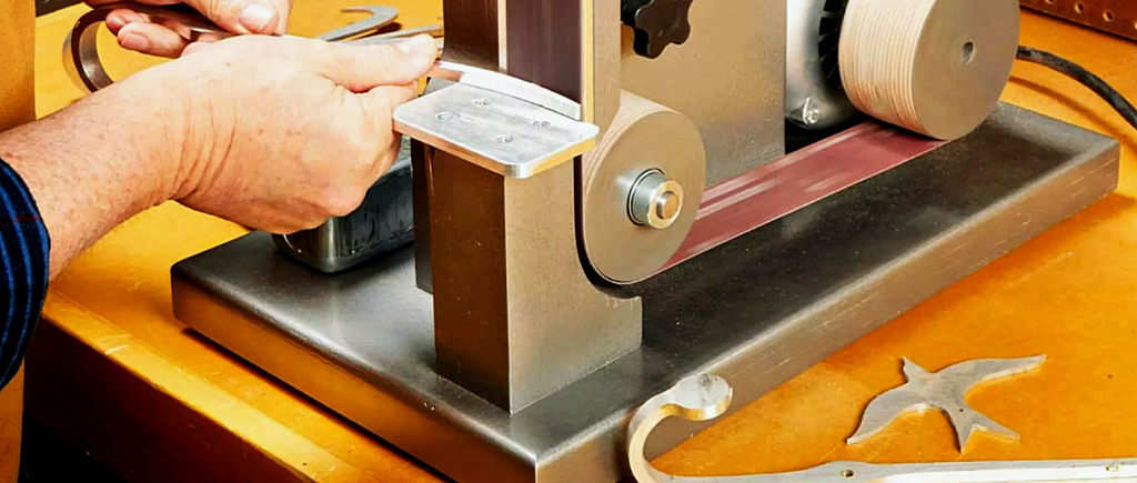
“Why build a power tool when you can just buy one?” I get that question a lot. The easy answer is to save money. And it’s true that the power tools shown in ShopNotes cost far less than commercial versions. There’s more to it.
Building your own tools allow you to customize the features: you can add qualities that improve your work — and leave off bells and whistles that offer little benefit.
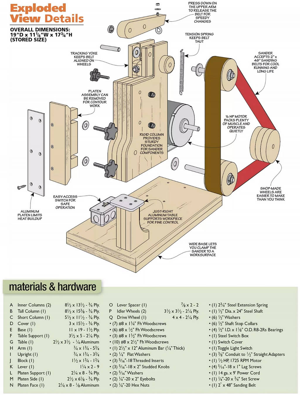
This sander offers a great case study. As you’ll see, the sander is built with a ruggedness that’s tough to match. We use high-quality components inside the machine so that it works right and is enjoyable to operate. (Thank you McMaster-Carr.) We picked a well-made motor that provides plenty of power and runs quietly.
The platen behind the belt is easily adjusted (or removed) to suit the task at hand. And speaking of the belt, there’s a very simple mechanism that applies tension and allows fast belt changes without requiring tools.
There’s one last thing you can do to take the project up a notch: give it a solid paint job. We like using the “hammered” finish spray paints that leave a wrinkled surface behind. It’s reminiscent of old tools and transforms bland plywood into a sharp-looking machine.
Strong Support, Big Column
The first part of the sander to make is the column. It reminds me of the stone tower formations so iconic in Western movies — or road runner cartoons. This column is more than a visual treat. It provides the main structure for the sander and supports the mechanical elements. Which means it has to be solidly constructed.
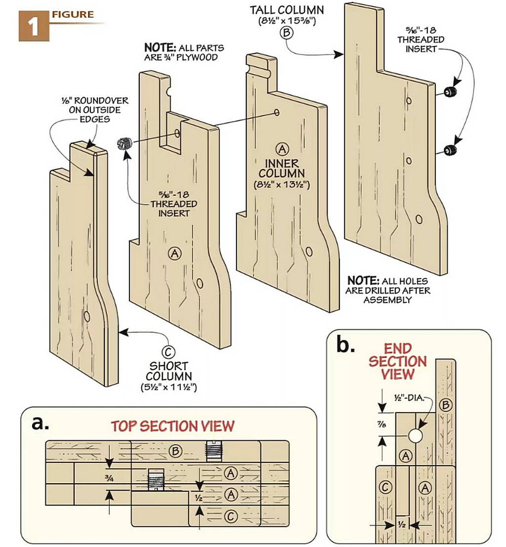
PLYWOOD CORE. Figure 1 shows that it consists of four layers of plywood. We used Baltic birch plywood for its consistent, void-free plies. You can use standard veneer core plywood as a lower cost alternative. Just be a little choosy in the pieces.
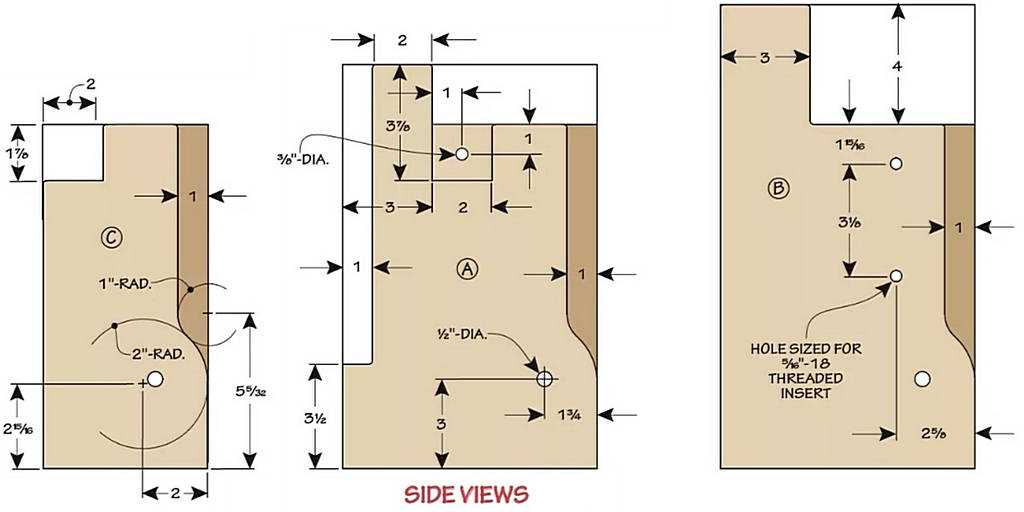
You’ll also notice that the four layers aren’t all identical. The two inner pieces are the same overall size, but the outer two are different. This has to do with the various parts of the sander that mount to the column. What the four parts do share is the front profile.
The two inner layers make a good jumping off point. Glue them up, then cut them to the size and shape, as shown in the drawings below. On one face there’s a shallow pocket that houses a tracking yoke you’ll get to later.
A good way to make it is by taping strips of plywood to define the perimeter of the pocket with double-sided tape. Then rout away the waste with a pattern bit. The bit won’t reach into the comers, so you need to square those up with a chisel. I left the guide strips in place as a way to keep the chisel square to the surface.
When adding the outer layers, I cut the back edge to the shape required. At the front, I traced the profile of the inner pieces and rough cut the waste. Once the new piece was glued on, a flush trim bit blended the two together.
HOLES. Take your column over to the drill press to drill the holes necessary for adding the mechanicals. A through hole near the bottom houses the lower wheel’s shaft. Another through hole near the top accommodates the shaft for the tracking yoke assembly. This is shown in Figure 1b.
The other holes that are required are for threaded inserts. The locations are shown in the drawings on the bottom of the previous page. One pair is used for attaching the sander’s platen and another is drilled into the pocket you routed earlier for the tracking adjustment knob, as shown in Figure la. Size the holes to match the “root” of the threaded insert.
TENSION & TABLE
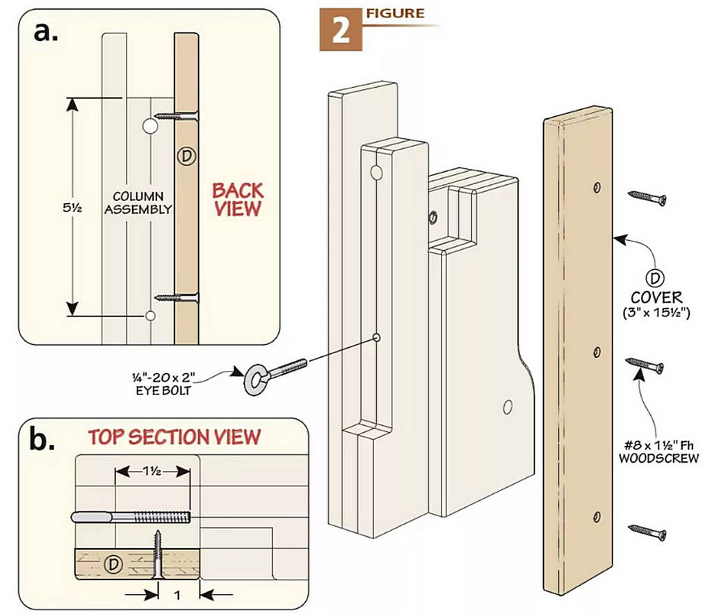
You aren’t done with the hole drilling yet. In Figures 2a and 2b you’ll see a hole on the back side of the column. An eye-bolt threads in here. It anchors a spring that applies tension to the upper wheel (and thus the sanding belt).
A cover strip conceals the channel for the spring (Figure 2). It’s attached with screws for easy maintenance access.
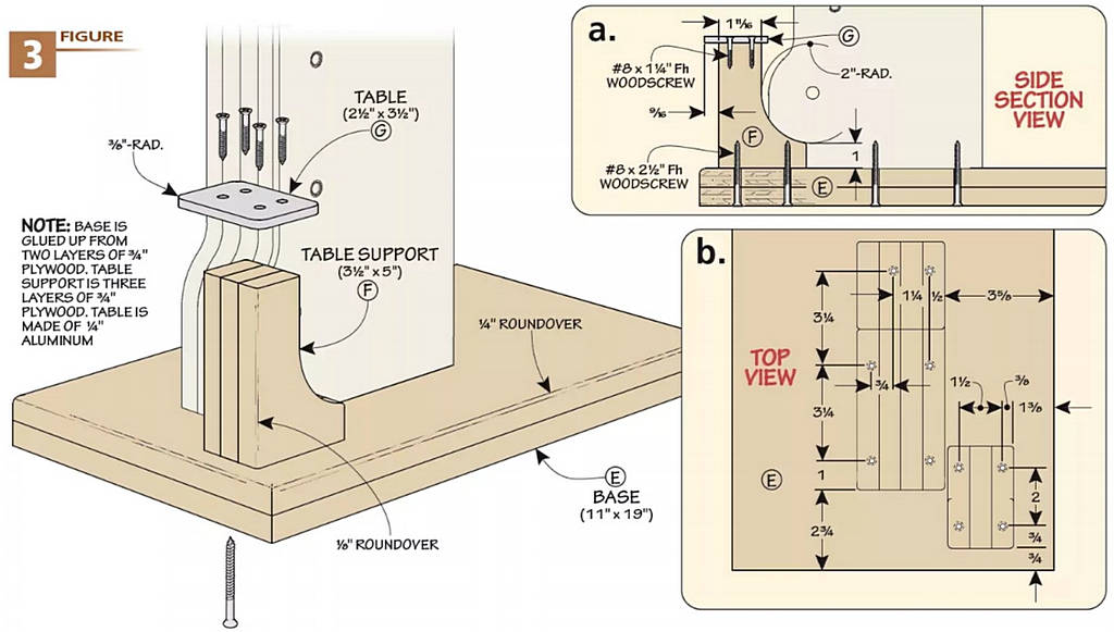
STABLE BASE. With the work on the column wrapped up, it’s time to make a base. You can see the base in Figure 3. It’s cut to final size from a blank made up of two layers of plywood. A round-over softens the upper edges.
Figure 3b shows the locations for the screws that connect the column to the base. It’s a good idea to drill pilot holes in the base before driving the screws. Otherwise you risk splitting the plywood layers.
TABLE. The next component on the to-do list is the table assembly (Figure 3). Think of it as the sidekick to the main column. The table support is glued up from three layers of plywood to resist flexing. The back of the support is relieved to allow the belt to run close to the table, as shown in Figure 3a.
The tabletop is a piece of aluminum. Using aluminum provides a durable, rigid surface. I find that it’s easy to work either by hand or with regular woodworking power tools. The four comers of the tabletop feature a radius to eliminate sharp edges.
Like the column, Figure 3b shows the locations for the screws to attach the table support to the base. Then it’s on to the fun parts.
The Right Amount of Tension
The fixed portion of the sander is complete and we can turn our attention to the clockworks. Up first is a dual-purpose tracking mechanism located at the top of the sander column.
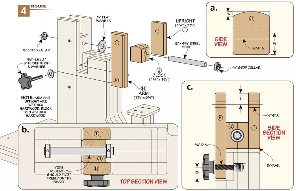
TRACKING YOKE. The tracking yoke is a Y-shaped hardwood assembly shown in Figure 4. It pivots around a steel shaft and allows an upper wheel to tilt side to side in order to keep the sanding belt running true in use.
The long arm of the yoke has a pair of holes, as shown in Figure 4c. The lower hole accommodates a studded knob used to dial in the tracking with finesse. The upper hole is for a steel shaft that holds a tension lever. Opposite the arm is an upright that also includes a shaft hole. The outside edges of these parts are eased with a roundover.
Sandwiched between the arm and upright is a thick block. A front-to-back hole in this block fits over a pivot shaft that runs through the column, as you can see in Figure 4b.
The upper edge of the block is rounded slightly to account for the tension lever that’s coming up. This curve is shown in Figure 4a.
ASSEMBLY & INSTALLATION. Glue up the yoke, making sure the shaft holes are aligned. A good way to do this is to slip a length of the shaft into the holes while the parts are clamped. The bottom of the block is held flush with the end of the upright.
Speaking of the shafts, Vi steel rod is used throughout this project. The first of these connects the yoke to the column. On one end, tighten down a stop collar. Fit that through the column from the back. Set the yoke into the pocket and thread the shaft through the block with a washer in between (Figure 4b). A second stop collar on the front end of the shaft completes the puzzle.
All that’s left is to add the studded knob and washer that twists into the threaded insert in the column, as in Figure 4c. The knob and yoke may seem loose now, but once a tension spring is added, it will all makes sense.

TENSION LEVER
With the tracking portion addressed, it’s time for some tension — the good kind. A stout hardwood lever holds the upper wheel of the sander on one end. On the other, is an extension spring that keeps the belt tight.
Let’s get going on the lever. Figure 5 above shows the finished part and how it fits in with the hardware elements. The drawing on the bottom of the previous page dives into the nitty gritty of making it. The comet-like shape allows it to clear the yoke.
Take note of the two holes that run side to side. One of these is for mounting to the yoke (Figure 5a). The other houses the shaft for the upper wheel (coming soon). Figure 5b highlights the hole at the tail to accept an eyebolt for the tension spring.
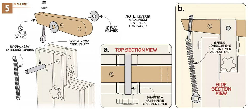
INSTALLATION. There’s nothing complicated about installing the lever. A pair of hex nuts and washers lock the eye-bolt in place on the tail.
Slip the shaft through the yoke, a pair of washers, and the lever. Then you can hook the spring over the eyebolt.
PLATEN ASSEMBLY. Working our way down the sander, we come to the platen assembly, as shown in Figure 6 below. This system backs up the belt, providing reinforcement for creating smooth, flat surfaces. However, there are times when you want to create a softened shape. So the platen is easily removable.
The platen support is plywood with beveled ends (Figure 6b). It’s screwed to the edge of the platen side. This piece has a pair of open slots that line up with the threaded inserts you installed in the column earlier.
I made the slots by drilling the ends at the drill press. After marking lines that run to the edge, I used a hand saw to remove the remaining waste. A little file work cleans up the edge.
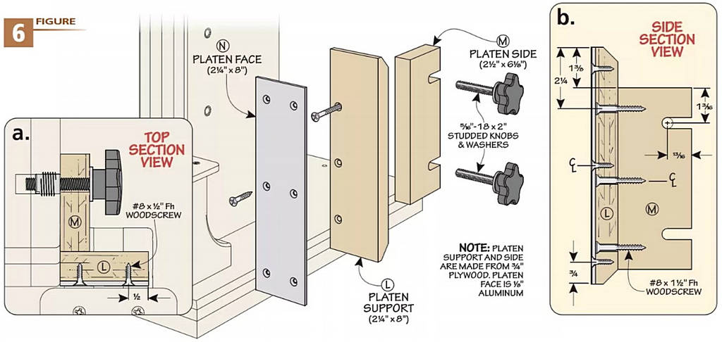
SMOOTH, DURABLE FACE. Combine the whizzing belt with the heat of sanding and you end up with something that would quickly wear down plywood. To cope with that, the platen is faced with a piece of aluminum. This is shown in Figure 6a. Use screws to attach the face. This way you can replace it down the road if it wears out.
This Last Part Is Wheel Nice
The final parts of the sander to make are the wheels. Using three wheels on this machine permits the use of a longer belt. The longer belt disperses heat better and results in longer life while reducing burning on the workpiece.
BUT FIRST, A SPACER. Before diving into the wheels, you need to add a spacer to the lever that you just made. The purpose of this piece is to align the upper wheel with the other two.
This round piece matches the radius of the lever’s nose (1″). A center hole is sized for the shaft. The “wheel side” of the spacer is chamfered, as shown in Figures 7 and 7b.
Take care when gluing the spacer to the lever. The holes need to align. Here again, using a shaft to ensure alignment.
IDLER WHEELS. Now it’s time to make wheels. And this process has a choose-your-own-ad venture element to it.
THE PATH OF THE LATHE. For those with a lathe, you can glue up wheel blanks made from three layers of plywood. Drill the through holes and counterbores that house the bearings (Figures 7a and 7b). After an interesting time at the lathe turning plywood, you have smooth, perfectly centered wheels.
NO LATHE, NO PROBLEM. If, like me, you don’t turn, then a different approach is necessary. You can use a wing cutter in the drill press to create the six discs for the idler wheels. Use the 1/4″ pilot holes to align the discs and glue them up in three layers.
Head to the drill press and use a 1/4″ bit to center the wheel and clamp it down. Drill a counterbore for a bearing. This is shown in Figures 7a and 7b. This is a dance since you need to re-center the wheel for each counterbore. The final step is to drill out the through hole to account for the size of the shaft.
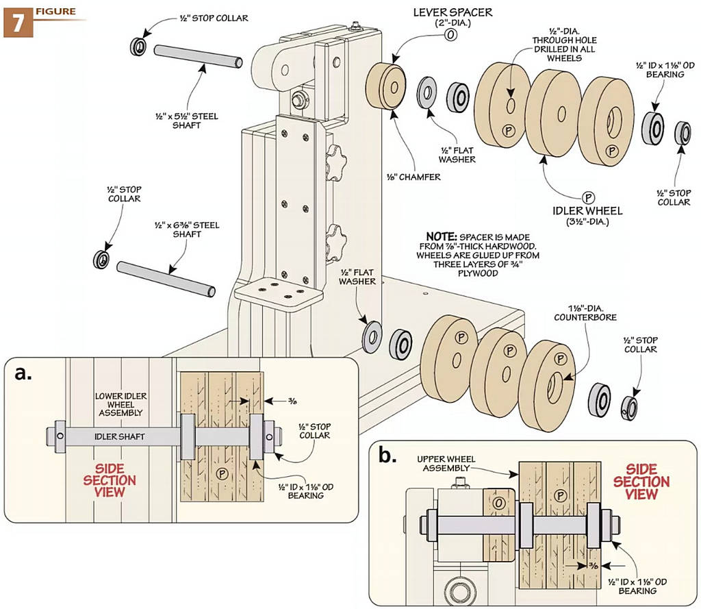
SPIN IT RIGHT ROUND. The two paths converge here. Press a bearing into each of the counterbores. Then it’s time to install the wheels. The two idler wheels are installed the same way. Cut the shafts to length and install a stop collar at one end. One passes through the lever, the other through the column.
Slide on a washer followed by the wheel. Cap off each shaft with a second stop collar. The wheels should spin without binding. Nor should they have much play side to side.
MOTORING ALONG
We’re ready to bring this sander to life. For that to happen, we need one more wheel… and a motor. Chris Fitch, the designer, spec’ed a 1/2 hp motor. It’s easy to find and reliable.
DRIVE WHEEL. The drive wheel is made similar to the others. Just note that it’s larger, as you can see in Figure 8. You don’t need to add bearings, so that makes it simpler. You do need to lock it to the drive shaft on the motor. Our motor includes a flat spot on the shaft for this purpose. In Figure 8a, you can see the solution. Drill a hole into the edge of the wheel and thread in a set screw. The screw will tap its own threads to secure it.
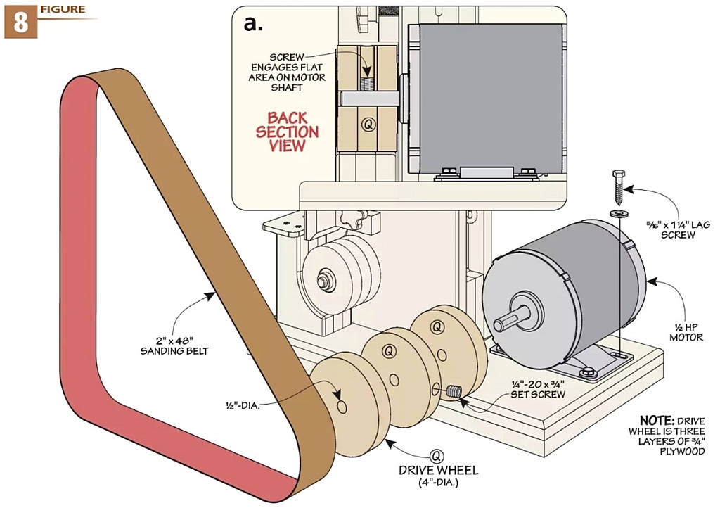
INSTALLING THE MOTOR. Set the motor on the back of the base. Now slip a sanding belt on the wheels. Adjust the position of the motor to align the wheels and determine its location on the base. Mark the location of the mounting holes. Drill pilot holes and attach the motor with lag screws. You’ll need to use a box wrench as the holes are partially obscured by the motor housing.
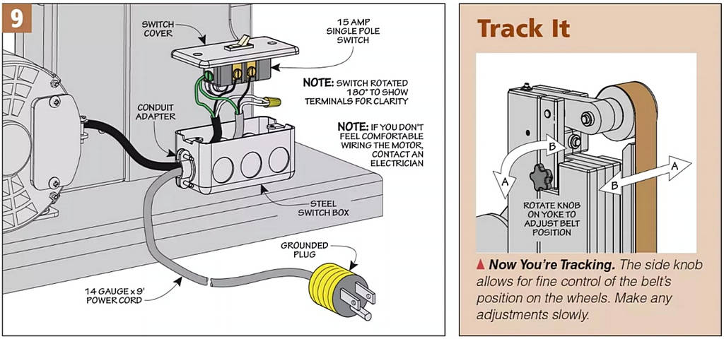
POWERED UP. I wired the motor to a switch mounted on the side of the base (Figure 9). At last it’s time to fire up the sander and put it to work — after you give it a paint job.
